
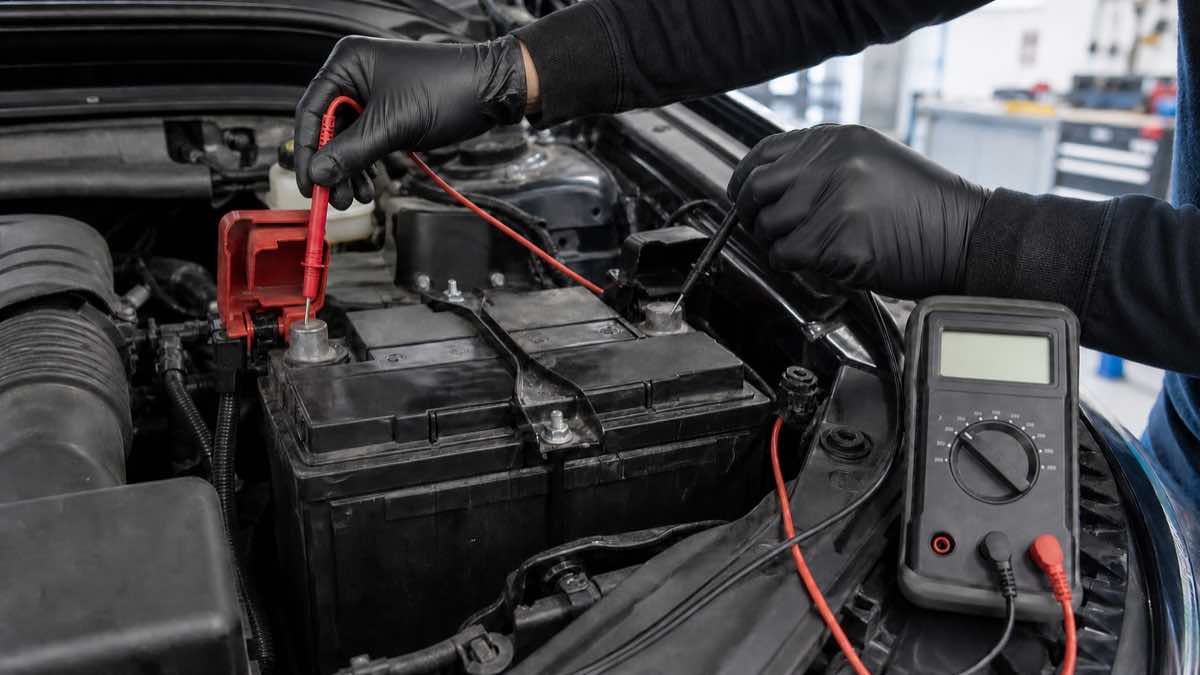
A digital multimeter can answer three basic automotive questions: Is voltage present? Is a wire or component path open? Is unwanted resistance stealing voltage while the circuit works? Those answers can narrow a no-start, dim light, blown fuse, weak ground, charging complaint, or intermittent electrical problem without replacing parts at random.
The tool is useful only when its leads, input jacks, dial, range, and circuit connection are correct. The most dangerous beginner mistake is leaving the red lead in an amp jack and placing the probes across a battery as if measuring voltage. That creates a low-resistance path through the meter and can blow its fuse, damage the meter, create sparks, or harm the circuit.
What an Automotive Multimeter Can and Cannot Do
| Measurement | Useful automotive question | Main limitation |
|---|---|---|
| DC voltage | Is electrical potential present at this point? | Voltage without load may not reveal a high-resistance connection |
| Voltage drop | How much voltage is lost across a cable, switch, ground, or connection while loaded? | Requires the circuit to operate under the correct condition |
| Resistance | Does an isolated component match its specified resistance? | Must normally be de-energized and may be affected by parallel circuit paths |
| Continuity | Is there a low-resistance path? | A beep does not prove the path can carry operating current |
| DC current | How much current flows through a circuit? | Inline measurement is easy to misuse and limited by the meter and fuse |
| Frequency or duty cycle | Is a repeating control signal present? | Requires suitable meter bandwidth and service information |
A multimeter provides a measurement, not the diagnosis by itself. The same voltage can be normal in one operating state and wrong in another. Compare readings with the exact wiring diagram, connector view, test condition, temperature, and manufacturer specification.
Choose the Right Multimeter for Car Diagnostics
A basic digital meter can handle many 12-volt checks, but quality and protection matter more than a long list of modes. Look for:
- DC voltage and millivolt ranges with enough resolution for voltage-drop testing.
- A high-input-impedance voltage function suitable for modern electronic circuits.
- Fused current inputs, clear jack labels, and preferably an alert for a lead left in the current jack.
- Min/max capture for brief cranking or intermittent events.
- Fast, reliable continuity response and a separate diode-test function.
- Durable, shrouded leads with sharp but controllable probe tips and optional back-probe accessories.
- Independent safety certification and ratings appropriate for every environment in which the meter will be used.
An automotive-specific meter may add RPM, temperature, pulse-width, dwell, or frequency functions. Those features help only when the vehicle procedure calls for them. A DC clamp meter can be safer and more convenient for some current tests because the circuit does not have to be opened, but its range and low-current resolution must match the job.
Know the Input Jacks Before Touching the Car
| Jack | Typical purpose | Beginner rule |
|---|---|---|
| COM | Black common lead | Black lead normally stays here |
| V/ohm | Voltage, resistance, continuity, diode, and often frequency | Use this red-lead jack for most automotive diagnosis |
| mA or microamp | Small current through a protected input | Never connect across battery voltage |
| A or 10A | Higher current within a strict rating and time limit | Series connection only; never across a battery |
Fluke’s DC voltage guide specifies the black lead in COM and red lead in the V/ohm jack. It warns that placing the probes in A or mA inputs and then measuring voltage creates a short in the measurement circuit.
After any current measurement, move the red lead back to the V/ohm jack immediately. This small habit prevents the next voltage test from becoming a short-circuit event.
The Pre-Probe Safety Routine
- Identify the circuit and expected value. Use a wiring diagram and service procedure instead of probing by wire color alone.
- Inspect the meter and leads. Do not use cracked insulation, exposed metal beyond the probe tip, loose plugs, a damaged case, or an unreadable display.
- Confirm the lead jacks. Black in COM; red in the correct jack for the selected function.
- Confirm dial and range. DC voltage is not AC voltage, resistance, or current. When uncertain on a manual-ranging meter, begin above the expected value.
- Confirm circuit state. Voltage and voltage drop use an energized circuit; resistance and continuity normally require an isolated, de-energized circuit.
- Secure the vehicle. Park or Neutral as specified, parking brake applied, wheels controlled, and a helper briefed before any start or load command.
- Control the leads. Keep them away from belts, fans that may start automatically, exhaust, sharp edges, and the hood latch.
- Verify the meter. Check it on a known source before and after a critical test so a failed lead or meter is not mistaken for a dead circuit.
Fluke’s multimeter safety guidance recommends inspecting the meter and probes for damage and verifying operation instead of assuming the tool works. It also explains that test-tool ratings must suit the measurement environment.
Test 1: Check DC Voltage Safely
Voltage is measured in parallel: the probes touch two points while the circuit remains intact. For a basic 12-volt check, put the black lead in COM, the red lead in V/ohm, select DC volts, and touch only the intended test points. A negative sign usually means the probes are reversed; it is not automatically a fault.
Use voltage to establish whether power reaches a fuse, relay, lamp, motor, module feed, or battery post. Record vehicle state with every reading: key off, accessory, key on, cranking, idling, load on, or load off. A number without its operating condition has little diagnostic value.
A battery-post voltage check can indicate state of charge under a defined condition, but it cannot fully measure battery capacity or health. Likewise, charging voltage depends on temperature, battery state, loads, smart-charging strategy, and manufacturer logic. Those two topics deserve their own complete procedures rather than one universal pass/fail number.
Test 2: Use Voltage Drop to Find Hidden Resistance
A damaged cable can show battery voltage at its far end when almost no current flows, then fail when a motor or lamp is loaded. Voltage-drop testing finds that restriction by measuring across the cable, connection, switch, fuse, relay contact, or ground while the circuit carries its normal current.
- Keep the red lead in V/ohm and select DC volts or millivolts as appropriate.
- Place one probe at each end of the section being tested.
- Operate the circuit under the condition that produces the fault.
- Capture the reading with min/max when the event is brief.
- Compare with the vehicle or component specification, then divide the path into smaller sections to locate the loss.
Fluke’s automotive voltage-drop explanation notes that a digital meter’s own test current is too small to expose many restrictions during a static resistance check. The circuit’s real operating load makes the fault visible.
Starter circuits are high-current and physically hazardous. A beginner should not reach a probe toward an exposed starter terminal near exhaust, moving parts, or an unsupported vehicle. A trained technician can use a model-appropriate procedure and secure leads before cranking.
Test 3: Continuity and Resistance on a Dead Circuit
Continuity mode sends a small test signal and usually beeps below the meter’s internal threshold. It is useful for an isolated fuse, switch, wire, or ground path. Resistance mode displays a numerical value that can be compared with a specification.
- Switch the circuit off, disconnect power as the service procedure requires, and verify it is de-energized.
- Isolate at least one side of the component when parallel paths could affect the result.
- Touch the probe tips together first and note lead resistance.
- Do not pierce insulation unless the approved repair procedure addresses sealing afterward.
- Never use resistance or continuity mode on an airbag, pretensioner, pyrotechnic disconnect, or high-voltage circuit.
A continuity beep proves only that the meter sees a low-resistance path under its tiny test current. A corroded connection may beep and still fail under load. Follow a suspicious continuity result with the appropriate loaded voltage-drop test.
Test 4: Check Fuses Without Guessing
An installed fuse can be checked for power at both test points with DC voltage when the circuit is supposed to be energized. Voltage on the supply side but not the load side may indicate an open fuse, although circuit design and switching state still matter.
For continuity, remove and isolate the fuse after making the circuit safe. A visual check alone can miss a small break. If a replacement fuse opens again, do not install a higher rating. Diagnose the short or overload that caused it.
Current Measurement: Treat It as an Advanced Test
Current is measured through the meter, not across the source. That requires opening the circuit and inserting the meter in series. The meter’s current input, lead, internal fuse, range, and time limit must all exceed the expected current. Connecting a meter in current mode across a battery can create a direct short.
Do not put a handheld meter in series with a starter, alternator output, electric cooling fan, blower on high, or another circuit that can exceed the meter’s rating. Use a correctly rated DC current clamp and a trained procedure for high-current testing.
Parasitic-draw testing is also more complex than disconnecting one battery cable and inserting a meter. Opening the circuit can wake modules, erase learned states, trigger alarms, or exceed the meter fuse when a door, light, pump, or computer activates. Modern vehicles need a sleep strategy, bypass or clamp method, service information, and a known acceptable draw for that configuration.
Three Diagnostic Patterns Worth Learning
Power is present but the component does not work
Confirm voltage at the component while it is commanded on, then test its ground side under the same load. If both are correct, use the wiring diagram and component procedure before condemning the part. A high-impedance meter may display “ghost” or back-fed voltage that cannot deliver useful current.
The circuit works intermittently
Use min/max capture, secure back-probes, and gently manipulate only the harness section allowed by the service procedure. Record temperature, vibration, load, steering position, door position, or weather when the fault appears. Avoid holding sharp probes by hand during a road test.
A warning light names a system
A multimeter may verify power, ground, reference voltage, or a basic sensor circuit, but it does not replace a scan tool. Diagnostic trouble codes and live data identify what the control module observed. Our check engine light guide explains why a code is a starting point rather than a replacement instruction.
Common Multimeter Mistakes on Cars
- Measuring battery voltage with the red lead still in the current jack.
- Using resistance or continuity on a powered circuit.
- Assuming a continuity beep means a cable is good under load.
- Probing the connector face and spreading or damaging terminals.
- Using body sheet metal as ground without confirming that the chosen point is valid.
- Comparing readings taken under different key, load, temperature, or module states.
- Back-probing sealed connectors with oversized pins and creating future water intrusion.
- Letting loose leads contact a belt, fan, exhaust, or another terminal.
- Using generic internet thresholds instead of vehicle specifications.
- Trying to diagnose an airbag, high-voltage, or network waveform with an unsuitable meter and procedure.
12-Volt, Hybrid, and EV Boundaries
This guide is limited to conventional low-voltage automotive circuits. Hybrids and EVs still have a 12-volt system, but it may wake contactors, pumps, computers, or charging hardware unexpectedly. Follow the manufacturer power-down and wake-up procedure even when testing only the low-voltage side.
Do not probe orange cables, traction-battery terminals, inverter connections, service disconnects, electric compressor circuits, or high-voltage interlock loops. High-voltage diagnosis requires model-specific training, personal protective equipment, rated tools, and verification procedures.
A Simple Measurement Worksheet
| Record | Your entry |
|---|---|
| Vehicle, engine, battery type, and circuit | ________________ |
| Complaint and operating condition | ________________ |
| Meter model, lead jacks, function, and range | ________________ |
| Probe point A and probe point B | ________________ |
| Key, engine, and load state | ________________ |
| Measured value and polarity | ________________ |
| Manufacturer specification and source | ________________ |
| Next test based on the result | ________________ |
This record prevents accidental comparisons between unlike conditions. It is especially useful when dashboard warnings appear only under load; use our dashboard warning lights guide to record the correct symbol before voltage changes or a battery disconnect alters the display.
If charging behavior is the concern, review the symptoms in our battery light guide. A multimeter reading should be interpreted alongside belt condition, battery state, commanded charging strategy, loads, and scan data.
Frequently Asked Questions
What multimeter setting is used for most car tests?
DC voltage is the most common starting function for a 12-volt vehicle. Keep the black lead in COM and red lead in V/ohm. Resistance, continuity, current, frequency, and diode modes require different circuit conditions and procedures.
Can any digital multimeter be used on a car?
A meter must be in good condition, independently certified, appropriately rated, and capable of the required resolution and function. Very basic meters may lack fused inputs, min/max capture, low-current accuracy, or protection suitable for the intended work.
Why does continuity beep but the circuit still fail?
The continuity test uses very little current. A damaged or corroded path may pass that tiny signal but lose excessive voltage under real load. Test voltage drop while the circuit operates.
Can a multimeter test whether a car battery is good?
It can measure voltage under defined conditions, but voltage alone does not fully test capacity, internal condition, or future reliability. Combine the reading with the correct battery-health or load test and vehicle specifications.
Can I test an alternator by disconnecting the battery?
No. Disconnecting a battery while the engine runs can create voltage disturbances and damage electronics. Use the manufacturer charging-system procedure, appropriate meter functions, scan data, and load conditions.
Can I measure parasitic draw with a multimeter?
Yes, but an inline current test is not a good first measurement for an untrained user. It can wake modules, erase states, or blow the meter fuse. A suitable DC clamp or fuse voltage-drop method may reduce disruption when used with a vehicle-specific sleep procedure.
Bottom Line
A multimeter for car diagnostics is most powerful when you choose the measurement before touching the probes. Use DC voltage to find electrical potential, voltage drop to expose resistance under load, and continuity or resistance only on a safe, isolated circuit. Treat direct current measurement as advanced work, return the red lead to V/ohm after using an amp jack, and never let one number replace the wiring diagram and manufacturer specification.